NEW: Proportional CANBus Mobile Valve Control
News for APV10 Mobile Valve Series
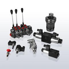
The AMCA mobile valve series is used for proportional, load-compensated control of hydraulic consumers. The mobile valves of this series can work with both LS pumps and fixed displacement pumps and are available in sizes APV10 (0-80 l/min), APV16, APV 22 and APV32 (0-1000 l/min).
New is the CAN bus controller AP-1020-356J and AP-1020-356K for proportional control of valve sections of size APV10..
Function of the CANBus controller in the valve section
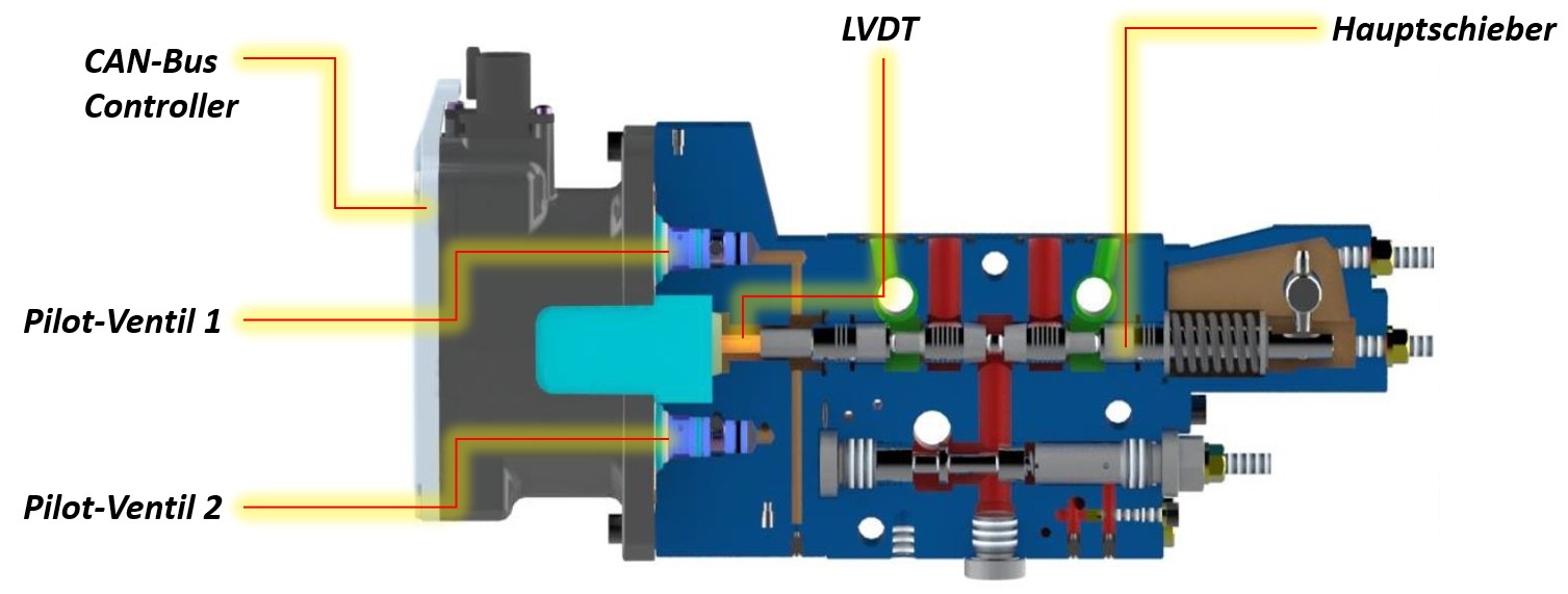
Up to now, the APV sections, or more precisely the main spool in the respective section, can be controlled manually, hydraulically or electrically. In addition, CAN bus control is now also available, which receives its setpoints and commands via bus communication from a higher-level control system and, conversely, can return status information. Directly integrated in this module are the pilot valves for proportional control of the main spool. An LVDT displacement signal transmitter for monitoring or control completes the bus controller.
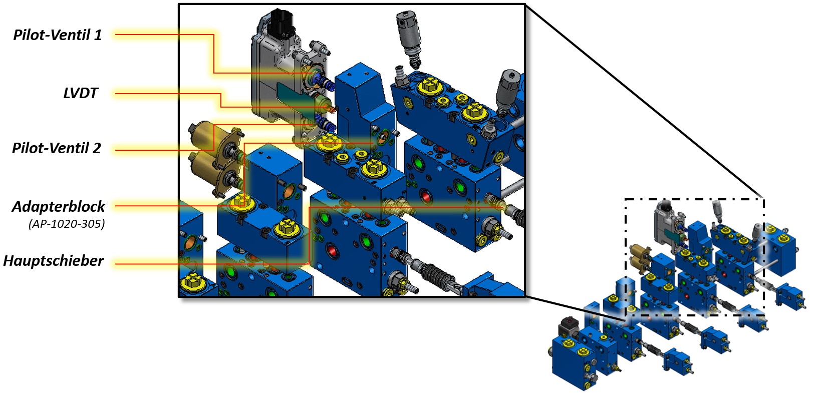
The CAN bus controller for controlling the APV10 valve sections is available as either a 12 VDC version (AP-1020-356J) or a 24 VDC version (AP-1020-356 K). The controller is flanged to the standard spool section with an adapter, the LVDT displacement sensor is connected to the main spool. The two pilot valves control the main spool on both sides, ensuring its proportional displacement.
Function of the CANBus Controller
The individual sections are combined to form the overall assembly. Different control types can also be combined in the configuration.
Overall Valve Assembly
Advantages of CANBus Technology
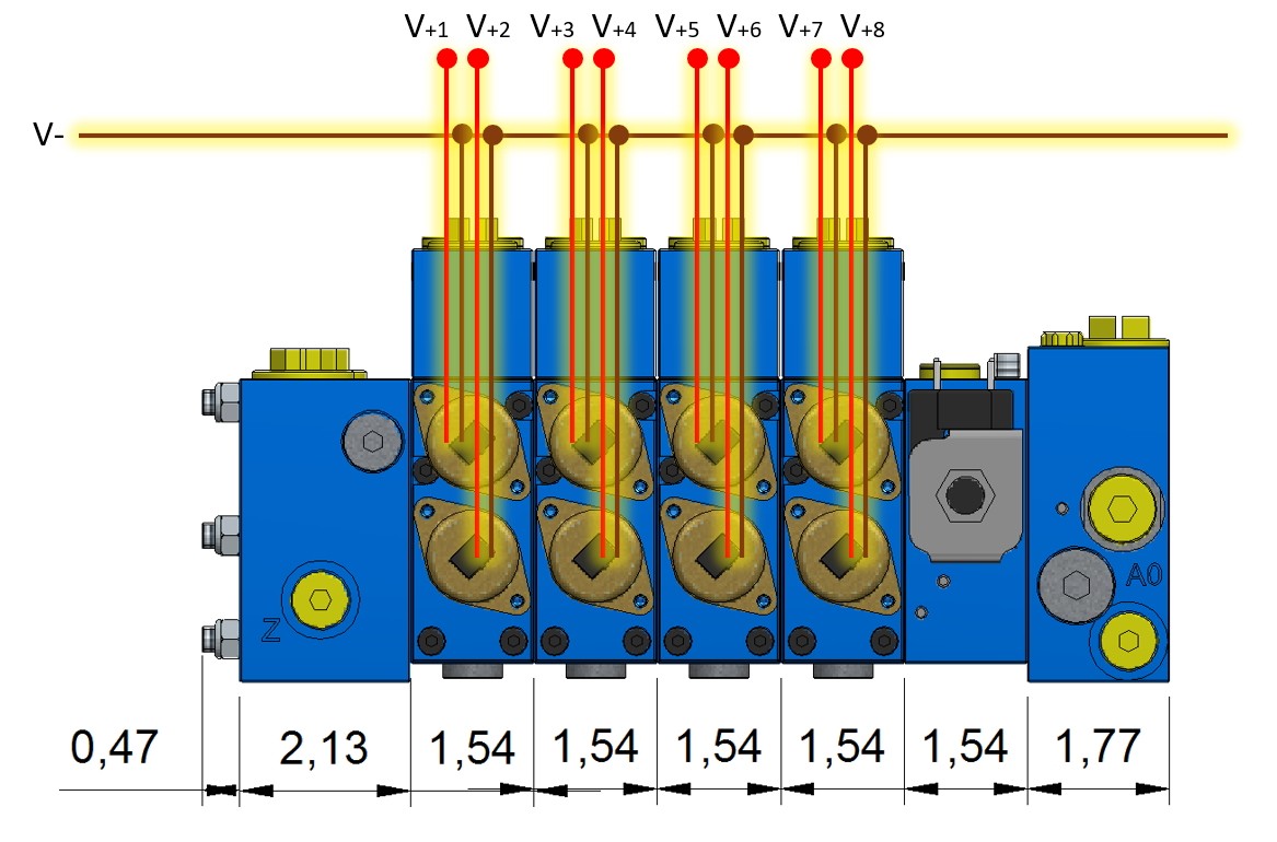
Simple Wiring
Control via CANbus provides particular advantages if a larger number of consumers is to be controlled, which corresponds to higher number of valve sections. With purely electrical control, each control solenoid requires individual wiring up to the machine control and an analog output per channel in the higher-level PLC (Programmable Logic Control).
Wiring effort for conventional electrical control
When using CANbus controllers, no additional outputs are required in the controller. Additional modules are only integrated into the CAN bus line with stub lines. The lines can thus be significantly shorter.
Monitoring Option
Another advantage of CANbus technology is the possibilities for monitoring the valve actuation. The integrated LVDT displacement sensor can reliably determine the position of the spool. Malfunctions, e.g. due to blocked spools or defective control coils, can thus be detected.

Advantages of CANbus Wiring
Fuctional Safety
The aspect of functional safety can also be covered with the CANbus controller. The integrated LVDT displacement sensor increases the diagnostic coverage level. The optional additional circulation or relief valve can be used to implement a secondary shutdown path that switches the system to a safe state when a critical state is detected.
Circuit Diagram, Hydraulic and Electrical Characteristics
Enclosed is the schematic of the CANbus controller. The CANbus setpoints of the main control are processed on the controller board. There are two current drivers on the board, which control the current for the pilot valves. Furthermore, the position of the main spool can be integrated into the control loop via the LVDT displacement sensor.
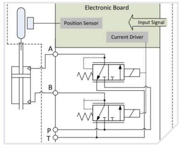
Electrical Schematic
A summary of the relevant electrical parameters is shown in the following table.
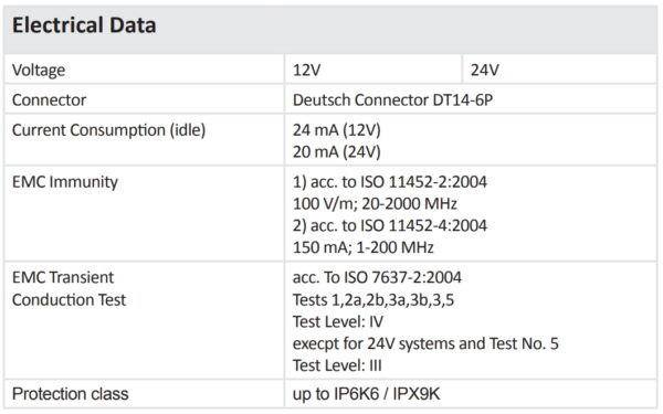
Electrical Data
In the idle state, the current consumption is 20 or 24 mA.
The hydraulic characteristics of the controller are shown below.
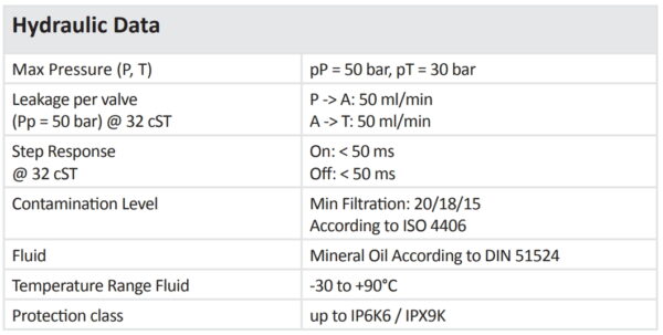
Hydraulic Data
The maximum supply pressure for actuating the pilot valves is 50 bar. The step response speed is 50 ms for a hydraulic oil of viscosity class ISO VG 32.
Electrical Connection, Communication and Configuration
Bus communication with the electrohydraulic actuator (EHA) is via the CANopen protocol according to CAI301/401.
The CAN controller has a 6-pin Deutsch connector DT14-6P (counterpart DT16-6SB). PIN 1 and PIN 5 are the power supply Vbat and GND. PIN 2 and PIN 6 are the CAN-Low and the CAN-High line. Furthermore there is an optional configurable analog input or output and the corresponding Ground (GND) connection (PIN 3 and PIN 4).
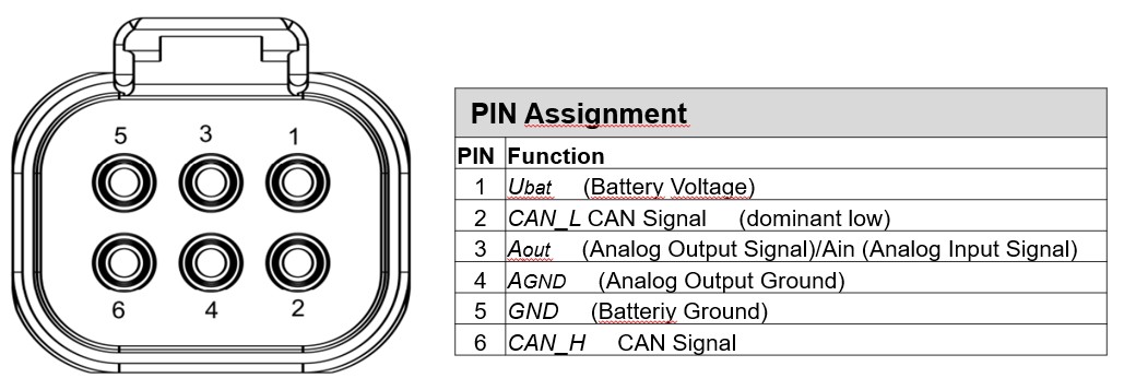
PIN-Assignment
The CAN lines are connected directly to the machine controller, individual bus nodes are added via a spur line if necessary.
The bus line must be terminated at both ends with a 120 Ohm terminating resistor. In many cases, the resistor is already integrated on the control side.
So that the valve sections can be addressed unambiguously, they must be given a unique address, a so-called node ID. The configuration is done via LSS command according to CIA DSP 305. A special software tool is available for the configuration. The baud rate is also configured via LSS.
Further information & CAN bus demo kit
To help you get started with CAN bus control, a CAN bus demo kit is available. In addition to the mobile valve and the CAN bus controller, this Demo-Kit kit also includes a mobile controller, two joysticks and the necessary harness.
Alternatively, the sections can of course also be configured customer-specific and combined with your own control system. You can find more information about this in our Web-Shop.
If you have any questions, please contact us directly or contact one of our local AMCA build partners for further support.