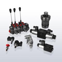
Mobile valves (AMCA)
Typical mobile valves are designed to serve the numerous consumers of mobile machines in a small installation space. A frequently cited example is excavators, where hydraulic consumers such as slew ring drive, boom cylinders, style cylinders and bucket cylinders are controlled. Here, many functions must be implemented in a load-compensated manner so that the movement is carried out independently of the respective load.
Common designs of mobile valves are sectional design or the so-called plate design.
![]()
, under this brand mobile valves have been developed and manufactured for more than 60 years. Two valve series are the APV series and the M series.
Are you looking for a valve solution for a stationary rather than a mobile application? No problem! Convince yourself of the many possibilities of the APV or the M series.

APV Mobile Valve Series
The AMCA APV control valve series is a highly modular valve design that is available in sectional and plate body designs. The APV series comes in four different sizes, APV10, APV16, APV22 and APV32 and covers a flow range between 80 l/min and 1000 l/min. It further features high pressure range up to 420 bar, low hysteresis and the optional salt and seawater resistant Protalloy coating. A worldwide dealer network of build partners can help you implement your solution.
The spool section is the central base. It consists of a spool section (I), basic or custom manifold blocks (II), and spring and end pens (III). In the APV10, for example, a maximum of 15 parallel sections are possible.
Conventional directional control valves control the start, stop and movement directions of hydraulic motors and cylinders. However, the speed of these users depends on the load pressure. If this load pressure varies then the speed is hardly controllable.
The AMCA proportional directional valves of the APV series are pressure compensated and achieve ideal control of force, speed, acceleration and deceleration, regardless of load and increased requirements. Load compensation is provided by the hydraulic pressure compensator (1), the spool at the bottom of the section.
There are different types of actuation for the APV section valve (2). Besides manual actuation, there are hydraulic actuation type and electric actuation type of the main spool.
Depending on the requirement, there are different types of gate valves (3). The most common main spools are the so-called A-piston for “closed center” applications and the so-called C-piston for “open center” applications. However, numerous other types are also available.
The connection block (II) is needed to meet the requirements of the customer’s application in terms of connections and other functions, and is screwed onto the top of the slide section. There are connection blocks with different primary and secondary safety functions, such as shock and post-suction valves, LS load limiting, etc.. Furthermore, the connection blocks are available in different thread versions BSP and SAE.
The sections are completed with an inlet and an end plate. These are used to adapt the valve configuration to the selected pump control. For example, an LS pump, in which the integrated LS controller automatically reduces the flow rate when the flow rate requirement is lower, requires a different input plate than a fixed displacement pump, in which an integrated pressure compensator must limit the flow rate that is not required.
Details about the APV series and the available configurations as well as brochures and STEP files can be found in our webshop.

APV mobile valve series as plate-mounted design
In addition to the sectional design, the APV series is also available in the so-called plate-mounted design. This is characterized by the fact that the individual control sections are connected via a common base plate. This can have advantages if certain connections and functions are to be additionally integrated into the common base plate. This type of construction is also very easy to maintain, as it is not necessary to dismantle all sections to access an internal disc for replacement, as is the case with the sectional construction. The affected unit can simply be unscrewed from the base plate and replaced by a new one.
A further advantage is that the slides and mounting options for the panel-mounted design are the same as for the sectional design, which reduces the variety of parts.
M-Series Mobile Valve
Another mobile valve is the M-Series. This series is listed purely as a plate-mounted version. That is, all required valve units as well as input plates are bolted onto a subplate section. A typical configuration consisting of input 3-way flow controller (1), subplate (2+4+6+7) and the MEV valve section with pilot and main control unit (3+5) is shown opposite. An overview of this series can be found in the media library, further details in the webshop.

Conventional directional control valves control the start, stop and directions of movement of hydraulic motors and cylinders. However, the speed of these loads depends on the load pressure. If this load pressure varies then the speed is hardly controllable.
AMCA M-Series proportional directional control valves are pressure compensated and achieve ideal control of force, speed, acceleration and deceleration, regardless of load and increased demands.
Pressure compensation can be accomplished with a pressure relief valve (MUV) or a pressure reducing valve (MDM) in combination with the throttling function of one or more directional control pistons. The pressure compensator acts here as a by-pass 3-way flow regulator (MUV) or as a series 2-way flow regulator (MDM).

The MEV is a proportional 4/3, 4/2 or 3/2-way valve. It is usually used as part of an overall configuration. Various spools are available.
The shape of the AMCA proportional control valve coil is different from other conventional coils. The result is a progressive flux curve. To make the best use of the coil’s maximum stroke, the inlet or outlet angle of the A and/or B port can be adjusted for higher flows. For constant flow, the pressure drop across the orifice of the spool remains constant, regardless of the load pressure.
The operation of the proportional directional valve with electrically controlled pilot stage (MEV) is explained below. When solenoid a is actuated, it pushes the control spool (control piston) toward solenoid b and opens spool cross-section 1. This releases control pressure to spring chamber 1 (speed controlled by adjustable orifice 5) and through orifice 3 to the end of the spool opposite solenoid a. The balancing force on the control spool is the force of the solenoid, which is proportional to the electrical input signal. The balancing force corresponds to the control pressure in the solenoid b and also in the spring chamber 1.This pressure presses the main spool against the spring in the spring chamber 2 and thus assumes a position proportional to the electrical input signal. The screws on the spring chambers can be used to limit the maximum flow by screwing in the screws and thus limiting the stroke of the main spool.

Two circuit diagrams and equivalent circuit diagrams for a configuration MUV + MEV as well as a configuration MDM + MEV is shown below.


The connections and other functions are located in the bottom plate.
The connections can be flexibly converted to BSP or SAE, for example. Special subplates are available for linking valve terminals.
Safety functions, e.g. LS pressure limits, can be integrated externally or in the subplate. The individual pressure setting can also be provided in the subplate.